目录
NK-RK3399-V0C
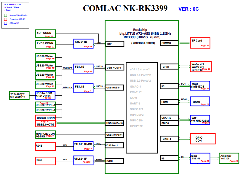
Motherboard frame diagram
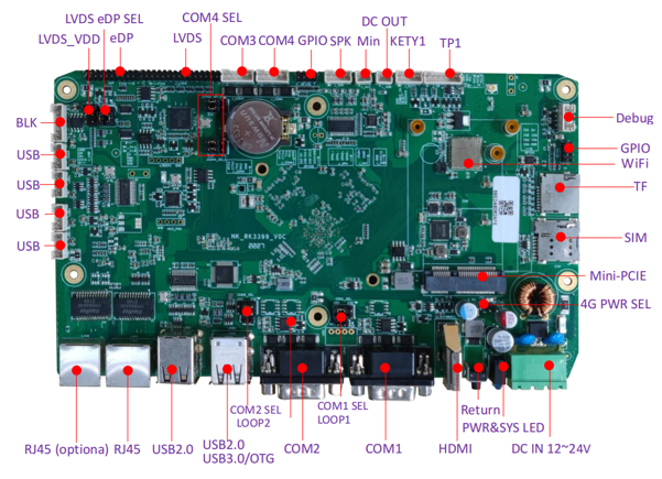
Interface definition
Contact pin definition
| Debug | COM1 | COM2 | USB1 | J5_LVDS-BLK | |||||||||||||
|---|---|---|---|---|---|---|---|---|---|---|---|---|---|---|---|---|---|
| 1 | NC | 1 | RS485_B1 | 6 | NC | 1 | RS485_B2 | 6 | NC | 1 | USB_VCC5 | 1/2 | GND/GND | ||||
| 2 | TX | 2 | A_RX1_CON | 7 | UART_RTS1_232 | 2 | A_RX2_CON | 7 | UART_RTS2_232 | 2 | HUB_USB_D3N | 3 | BL_PWM_OUT | ||||
| 3 | RX | 3 | UART_TX1_232 | 8 | UART_CTS1_232 | 3 | UART_TX2_232 | 8 | UART_CTS2_232 | 3 | HUB_USB_D3P | 4 | BL_EN_OUT | ||||
| 4 | GND | 4 | NC | 9 | NC | 4 | NC | 9 | NC | 4 | GND | 5 | LVDS_BK_IN | ||||
| 5 | GND | 5 | GND | 6 | LVDS_BK_IN | ||||||||||||
| GPIO1 | GPIO2 | LVDS输出接口 | eDP输出接口 | |||||||||||||||
|---|---|---|---|---|---|---|---|---|---|---|---|---|---|---|---|---|---|---|
| 1 | GPIO0 | 5 | GPIO2 | 1 | GPIO4 | 5 | GPIO6 | 1 | VDD | 16 | CLK_A+ | 1 | VDD | 11 | NC | |||
| 2 | VCC5_IO | 6 | GPIO9 | 2 | VCC5_IO | 6 | GPIO11 | 2 | VDD | 17 | Data_A3- | 2 | VDD | 12 | NC | |||
| 3 | GPIO1 | 7 | GPIO3 | 3 | GPIO5 | 7 | GPIO7 | 3 | VDD | 18 | Data_A3+ | 3 | GND | 13 | GND | |||
| 4 | GPIO8 | 8 | GND | 4 | GPIO10 | 8 | GND | 4 | GND | 19 | Data_B0- | 4 | GND | 14 | GND | |||
| 5 | GND | 20 | Data_B0+ | 5 | TX0N | 15 | AXUN | |||||||||||
| 6 | GND | 21 | Data_B1- | 6 | TX0P | 16 | AXUP | |||||||||||
| 7 | Data_A0- | 22 | Data_B1+ | 7 | TX1N | 17 | GND | |||||||||||
| 8 | Data_A0+ | 23 | Data_B2- | 8 | TX1P | 18 | GND | |||||||||||
| 9 | Data_A1- | 24 | Data_B2+ | 9 | NC | 19 | 3.3V | |||||||||||
| 10 | Data_A1+ | 25 | GND | 10 | NC | 20 | HPD | |||||||||||
| 11 | Data_A2- | 26 | GND | |||||||||||||||
| 12 | Data_A2+ | 27 | CLK_B- | |||||||||||||||
| 13 | GND | 28 | CLK_B+ | |||||||||||||||
| 14 | GND | 29 | Data_B3- | |||||||||||||||
| 15 | CLK_A- | 30 | Data_B3+ | |||||||||||||||
Jump_sel
| COM1_SEL | COM2_SEL | LVDS_SEL | BLK_SEL | XXXX | |||||||||||||||
|---|---|---|---|---|---|---|---|---|---|---|---|---|---|---|---|---|---|---|---|
| 1 | 3 | RS232 | 1 | 3 | RS232 | 1 | 3 | EDP | 1 | 2 | 3.3V | ||||||||
| 2 | 4 | 2 | 4 | 2 | 4 | 3 | 4 | 5V | |||||||||||
| 3 | 5 | RS485 | 3 | 5 | RS485 | 3 | 5 | LVDS | 5 | 6 | 12V | ||||||||
| 4 | 6 | 4 | 6 | 4 | 6 | ||||||||||||||
Hardware Characteristics
| Hardeware resource specification | |
|---|---|
| SOC | Rockchip RK3399 (28 nm HKMG processing) |
| CPU | ARM® six-core 64-bit processor with a dominant frequency of up to 1.8GHz Based on big.LITTLE size nuclear architecture, Dual Core Cortex-A72(Large Core) + Quad-core Cortex-A53(Small core) |
| GPU | ARM® Mali-T860 MP4 Quad-core GPU support OpenGL ES1.1/2.0/3.0/3.1, OpenVG1.1, OpenCL, DX11 support AFBC(Frame buffer compression) |
| NPU | |
| ISP | |
| CODEC(coder and decoder) | |
| memory | 4GB LPDDR4(2GB/4GB optional) |
| storage | 16G/32G/64G optional |
| Ethernet | 2*1000Mpbs ( optional ) |
| WIFI | 2.4GHz single frequency WiFi / 2.4G/5G dual-band |
| video output | support eDP. LVDS1080P. HDMI2.0 |
| video input | |
| audio | 2*SPK ( 6W 8Ω ) |
| SATA | |
| USB | 3*USB2.0 1*USB3.0 |
| power supply | DC IN 12~24V |
| Other | |
| Hardware electrical characteristics | |
| High and low temperature environment | -20℃~60℃ |
| static electricity | Meet ESD level 3 ,Contact discharge 6KV,Air discharge 8KV |
| Other | Meet EFT GB/T 17626.4-2008 level 3 |
Get started quickly
Win server
Linux System download
Debain : Debian Download link
Android System download
Android: System download link
OTG Driver Download
Buening tool download
System burning
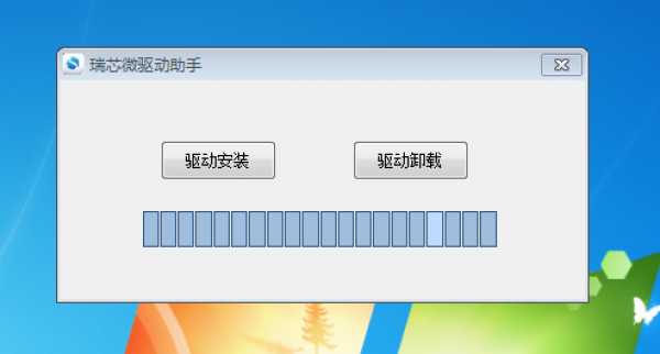
1、Download the buring tool:
- Be sure to install the driver first. The burning tool link contains driver DriverAssitant ziitant package, extract it and click DriverInstall.exe to install the driver.
2、Start Burn:
- Connect one end of the data cable to the OTG of the motherboard and the other end to the computer. Note that before burning, the power should be turned off. Press and hold the boot_key button to burn when the power is turned on.
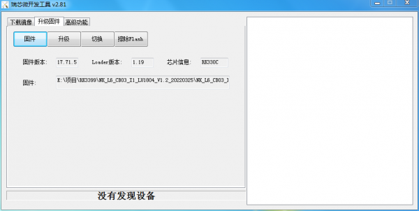
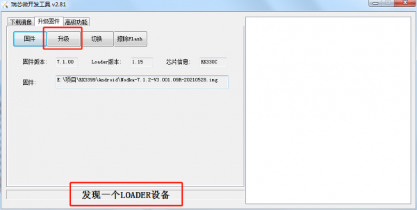
- Open the development tool in the compressed package, click Upgrade firmware first, then click firmware and select good firmware, and finally click upgrade to start burning.
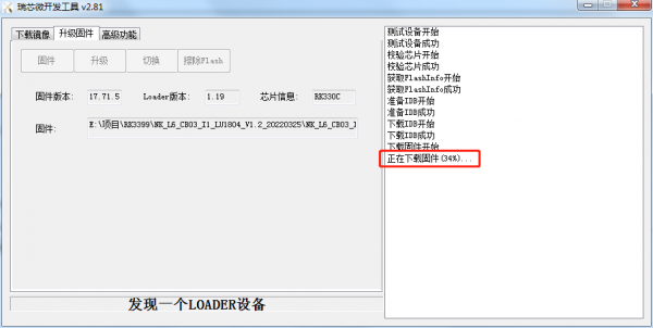
- The state of the burning process, there will be a progress display.
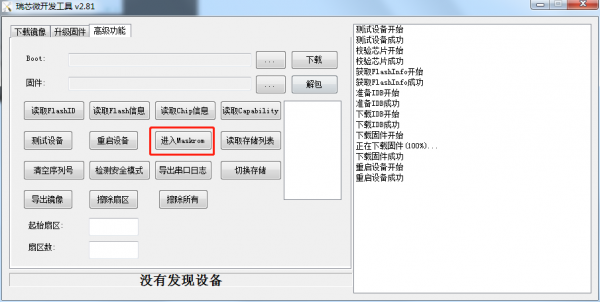
- When changing the system platform (such as switching from Android to Linux), it may fail to burn. At this time, open the development tool, click advanced functions first, and then click into Maskrom to switch the burning mode and then burn the system。
3、Finish burning:
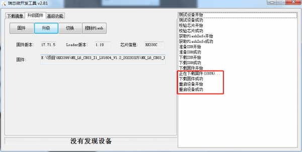
- There is no need for any operation in the process of burning. After successful burning, the right box will show that the device restarts automatically and the burning is complete.
Serial debugging
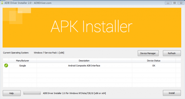
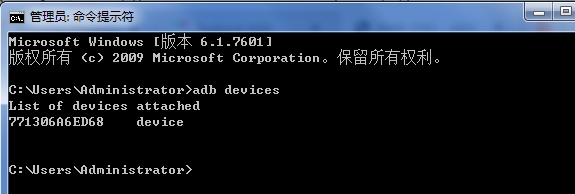
Android ADB
Linux SSH
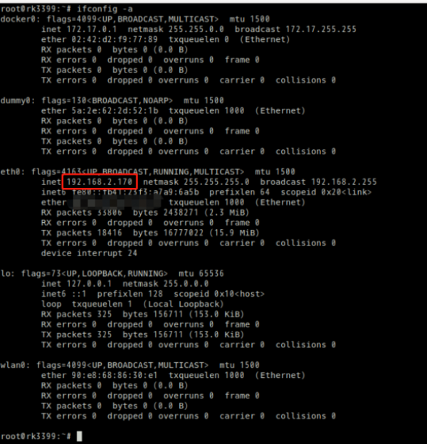
1. Enter the ifconfig command on the tablet to view the IP address:
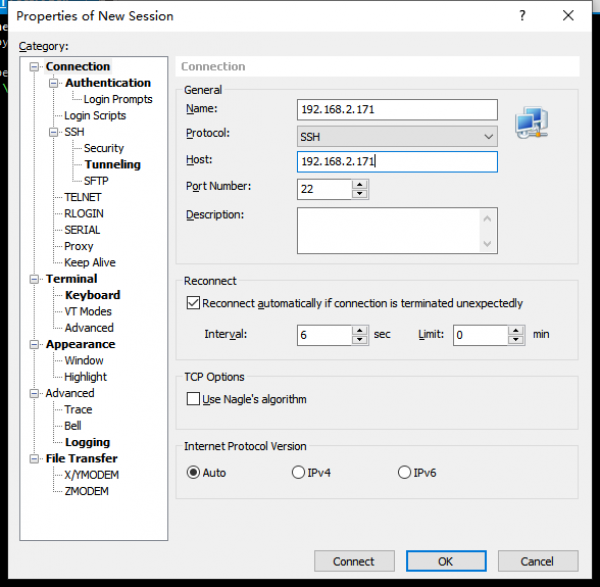
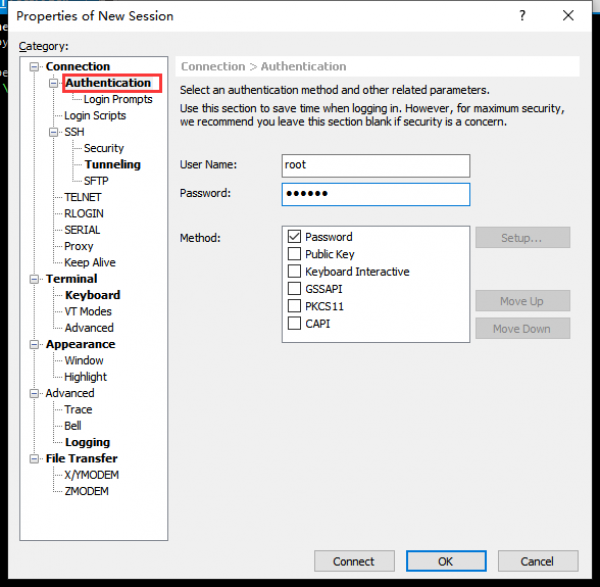
2. Open an SSH connection tool, such as putty, on the PC. The following uses xshell as an example:
As shown in the picture, enter the tablet IP address for host, and select 22 as the port number
3. User authentication
User:root
Password: 123456
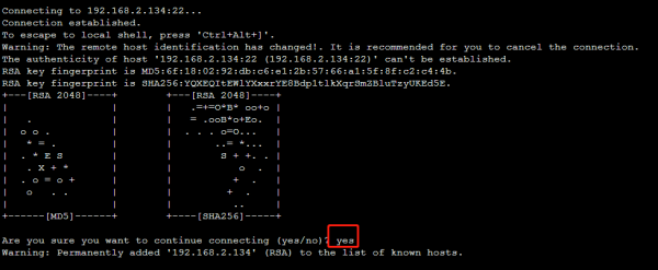
4. Click Connect. ssh key authentication is displayed:
Android user manual
Interface function test
UART
1. 串口定义参考:
2. 安卓系统串口设备节点对应表:
| 主板丝印 | 设备节点 |
|---|---|
| UART0_TTL | /dev/ttyS0 |
| RS232_Rx5/Tx5 | /dev/ttyS1 |
| RS232_Rx3/Tx3 | /dev/ttyS2 |
| RS232_Rx4/Tx4 | /dev/ttyS3 |
| RS485_A1/B1 | /dev/ttyS4 |
| RS485_A2/B2 | /dev/ttyS5 |
3. ComAssistant 测试串口通讯,以232_Rx5\Tx5回环测试为例
- 参考步骤1~2短接232_Rx5\Tx5的 Tx & Rx (1-2 pin)
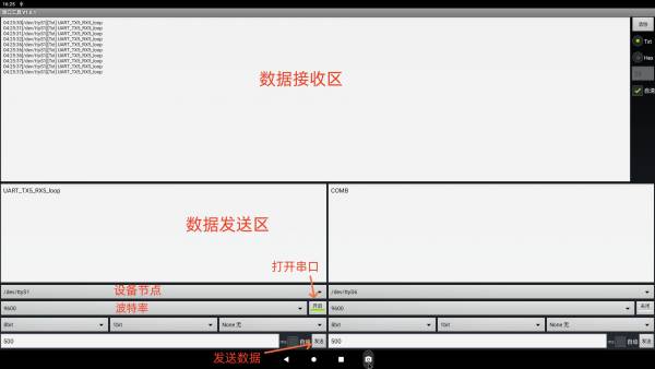
- 打开ComAssistant APP,设置好串口参数:
  波特率:9600
  数据位:8bit
  起始位:1bit
  校验位:none
- 设置好串口参数后,打开串口,在数据发送区输入框中输入字符,点击发送,可以发送数据。如下图所示:
4. RS485测试通讯,不支持回环测试,测试方式:
- 通过USB转RS485工具,与上位机(Windows端)互测
- 通过RS485转RS232工具,与RS232互测
- 两个RS485对发测试
LAN
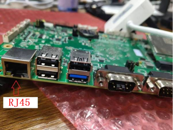
1. Connect the network cable to the LAN1 port on the mainboard.
2. View the IP address of a network adapter
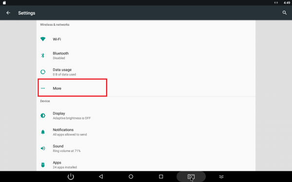
a)Click Settings first, then more.
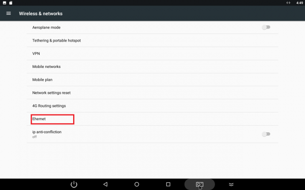
b)Click Ethernet.
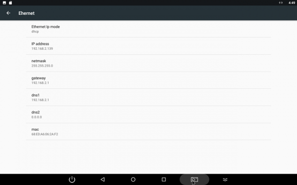
c)View an IP address. The system dynamically obtains an IP address by default.
3. After connecting to the network, open the browser and browse the web page to check whether the network is connected.
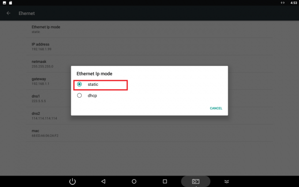
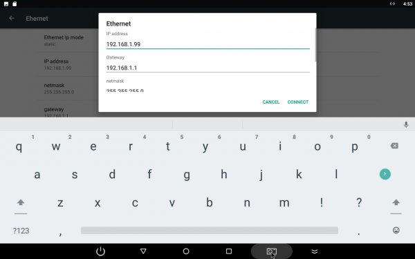
4.Set a static Ethernet IP address.
* Click Ethernet IP mode and select static.
* Set up.
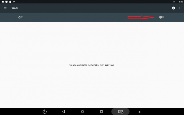
WIFI
4G/5G
Can
GPIO/DIO
Audio
连接扬声器后,可播放音视频,测试左右声道
Mic
接好麦克风和一对喇叭后,使用系统内置的录音机APP,录音和播放测试
USB
SDCARD
5.1 插入TF卡至设备TF卡卡槽
5.2 上滑至应用页面 » 文件 » 查看外接TF卡信息
5.3 在系统下拷贝文件至TF卡,进行读写测试
5.4 上滑至应用页面 » 文件 » TF卡挂载名称 » 点击旁边的弹出图标,弹出TF卡
Bluetooth
WatchDog
Key
- 3pin-GND:power_on功能:poweroff状态下启动系统
- 4pin-GND:Reset功能:重启
- 5pin-GND:Recovery_key:Android-返回键;Linux-无
LCD
1.LVDS
a)Connect the data line with the pin correctly, connect the backlight line, and connect the contact control line, and pay attention to the short position of the jumper cap.
LVDS may not display content at first and may need to adjust the resolution to the one LVDS requires.
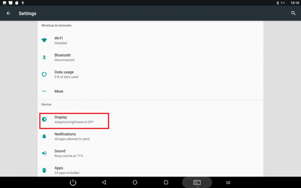
b)Open Settings and click Show.
c)Click on resolution and enter your password.
d)Select the resolution you want for your LVDS screen.
2.eDP
a)Connect the data line with the pin correctly, and connect the backlight line. Pay attention to the short connection position of the jumper cap.
The eDP may not display content at first, and the resolution needs to be adjusted to the resolution required by the eDP.
b)Open Settings and click Show
c)Click on resolution and enter your password
d)Select the resolution you want for the eDP screen
PowerManager
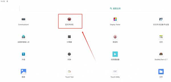
支持在线升级,系统内置升级APP,打开可查看是否有最新系统版本
RTC
1.Enter date on the terminal to view the current RTC time.
2.Enter “date -s + time format “to set the current time.
3.Enter hwclock -w to save the time and restart the mainboard.
Set basic system functions
System performance test
- 查看CPU信息
cat /sys/devices/system/cpu/cpu*/cpufreq/cpuinfo_cur_freq  //查看cpu频率
cat /sys/class/thermal/thermal_zone0/temp //查看CPU当前温度
- 查看内存信息
free -h
- 查看存储信息
df -h
- 查看USB设备
lsusb
Android API instructions
NodkaAPI entry class
NodkaAPI method of application:
1、Create the NodkaAPI instance in onCreate of the Application.
mNodkaAPI = NodkaAPI.nodkaAPICreate(this);
2、Use API steps in an Activity or Fragment:
private NodkaAPI mNodkaAPI = APIApplication.getApplication().getNodkaAPI();
NodkaAPI interface specification:
1、Beginning with devinfo is the hardware and system information query class api.
2、Starting with display is the display control class api
| Interface class | Method Name | method statement |
|---|---|---|
| Hardware and system information query class | devinfo_getAndroidVersion() | Obtain the Android OS version |
| devinfo_getAvailMem() | Obtain the available memory capacity | |
| devinfo_getBuildNumber() | Obtain the system version information | |
| devinfo_getCpuCores() | Obtain the number of cpu cores | |
| devinfo_getCPUCurFreqKHz() | Obtain the current cpu operating frequency | |
| devinfo_getCPUMaxFreqKHz() | Obtain the maximum cpu frequency | |
| devinfo_getCPUMinFreqKHz() | Obtain the minimum cpu frequency | |
| devinfo_getCPUTemp() | Obtaining the cpu temperature | |
| devinfo_getDeviceModel() | Obtain device model information | |
| devinfo_getKernelVersion() | Obtain the kernel version information | |
| devinfo_getSdStoragePath() | Obtain the SD card path | |
| devinfo_getSerialNum() | Obtain the device SN | |
| devinfo_getStorageAvailableSize() | Gets the local available storage capacity | |
| devinfo_getStorageTotalSize() | Get native storage capacity (excluding system partitions) | |
| devinfo_getTotalMem() | Obtain the total memory capacity | |
| devinfo_getUsbStoragePath() | Obtain the USB flash drive path | |
| Display control class | display_getNavBar() | Gets whether to display navigation bar and status bar |
| display_getScreenBrightness() | Get screen brightness | |
| display_getScreenMode() | Get the brightness adjustment mode | |
| display_getScreenRotation() | Gets the screen rotation direction | |
| display_getWindowHeight() | Gets the screen resolution height | |
| display_getWindowWidth() | Gets the screen resolution width | |
| display_setNavBar(java.lang.Boolean enable) | Set whether to display the navigation bar and status bar | |
| display_setNavBarSlideShow(java.lang.Boolean enable) | Set whether swiping displays navigation and status bars | |
| display_setScreenBrightness(int screenBrightness) | Set screen brightness | |
| display_setScreenMode(int screenMode) | Set the brightness adjustment mode | |
| display_setScreenRotation(int rotation) | Set the screen rotation direction |
Linux user manual User's Guide Pitaschio
Test Interface
GPIO
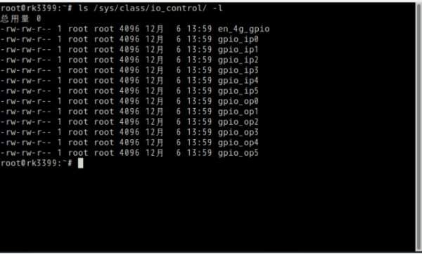
1.IO - Control Node:ls /sys/class/io_control -l
2.IO - Corresponding form as follows:
| function | Screen printing of motherboard | Node name |
|---|---|---|
| input | IO1 | gpio_ip0 |
| IO2 | gpio_ip1 | |
| IO3 | gpio_ip2 | |
| IO4 | gpio_ip3 | |
| IO5 | gpio_ip4 | |
| IO6 | gpio_ip5 | |
| output | IO7 | gpio_op0 |
| IO8 | gpio_op1 | |
| IO9 | gpio_op2 | |
| IO10 | gpio_op3 | |
| IO11 | gpio_op4 | |
| IO12 | gpio_op5 |
3.IO control method:
- Output low level:
echo 0 >/sys/class/io_control/gpio_op0
*Output high level:
echo 1 >/sys/class/io_control/gpio_op0
*View input level:
cat /sys/class/io_control/gpio_ip0
UART
1. Serial port definition reference:
2. A serial port device node system corresponding to the table:
| Screen printing of motherboard | Device node |
|---|---|
| COM1 | /dev/ttyXRUSB0 |
| COM2 | /dev/ttyXRUSB1 |
| COM3 | /dev/ttyXRUSB2 |
| COM4 | /dev/ttyXRUSB3 |
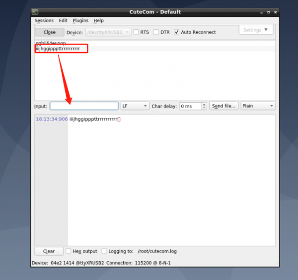
3. CuTecom test serial port to COM3 loopback test, for example
- Refer to step 1 ~ 2 sub COM3 TX and RX (2 ~ 3 pin).
- Double-click the desktop CuteCom icon to open the APP, Device selection test port corresponding Device node (see step 2).
- Click Settings to set the serial port parameters, as shown in the picture below:
- Set up after click Open to Open the serial port, input characters in the input text input box, and press enter to send data:
4. Command line mode test serial port, the same COM3 loopback test, for example
Open the terminal and enter the following command to receive data:
com_recv /dev/ttyXRUSB2 115200
Open another terminal to send data:
com_send /dev/ttyXRUSB2 115200
The test result is given as:
LAN
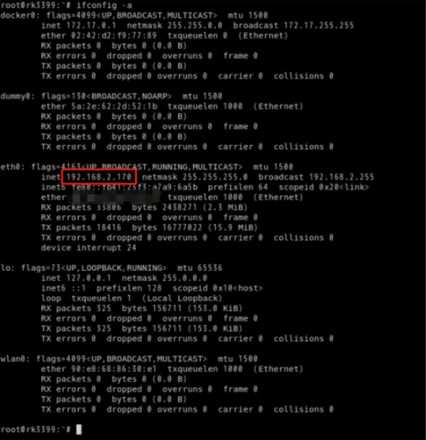
1. Check the network card IP address, the system will default to get the dynamic IP address
#ifconfig -a
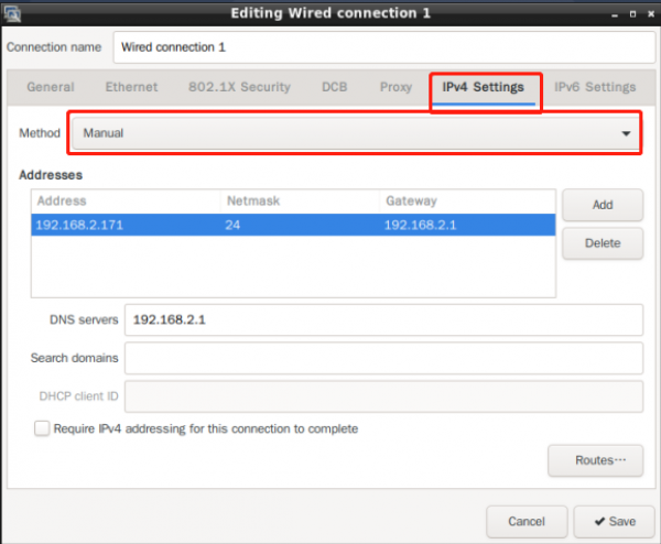
2. Set the static IP address of the NIC
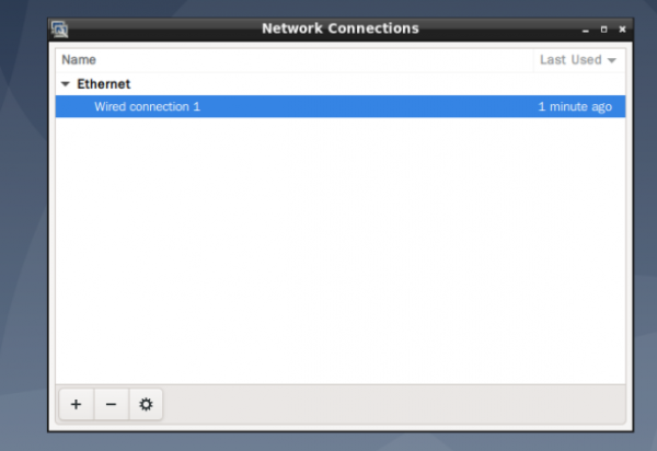
- Method 1 – Set up using graphical interface tools
Double-click the desktop icon:Advanced Network Configuration
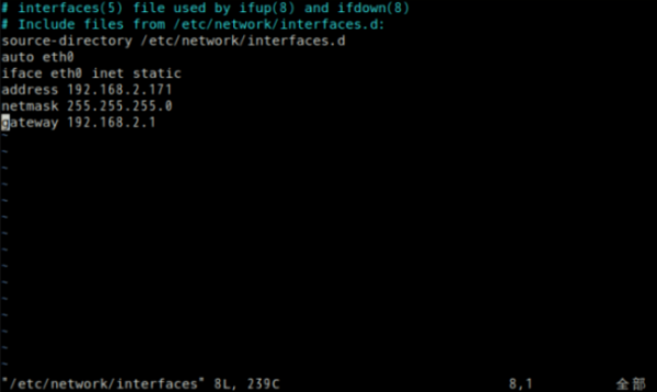
- Method 2 – How to modify the configuration file:
vim /etc/network/interfaces
- After the modification is complete, enter restart to take effect.
WIFI
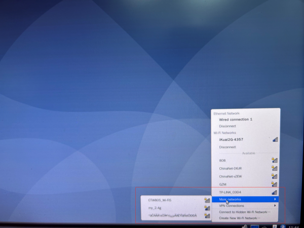
1. Click the network icon in the lower right corner to browse the available WIFI routes:
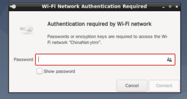
- Enter your WIFI password and click connect
2. Method 2 – Connect to wifi from the command line
nmcli d wifi connect "SSID" password "PASSWROD"
4G/5G
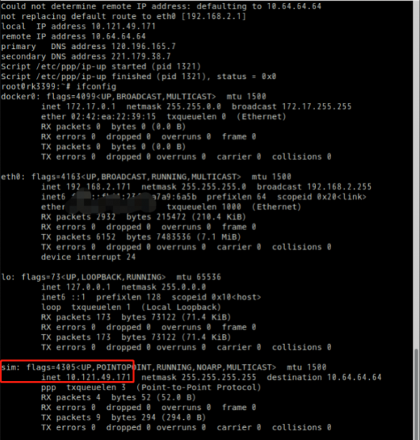
1. The system has automatic dialing, Open the terminal and enter the command 4g to dial automatically:
root@rk3399:~# 4g
2. After the dial-up is complete, view the IP address:
3.Open a browser and browse any website.
4. The 5G test method is similar to 4G, and the command 5G can be automatically dialed:
root@rk3399:~# 5g
Can
GPIO/DIO
1.IO - Control Node:ls /sys/class/io_control -l
2.IO - Corresponding form as follows:
| function | Screen printing of motherboard | Node name |
|---|---|---|
| input | IO1 | gpio_ip0 |
| IO2 | gpio_ip1 | |
| IO3 | gpio_ip2 | |
| IO4 | gpio_ip3 | |
| IO5 | gpio_ip4 | |
| IO6 | gpio_ip5 | |
| output | IO7 | gpio_op0 |
| IO8 | gpio_op1 | |
| IO9 | gpio_op2 | |
| IO10 | gpio_op3 | |
| IO11 | gpio_op4 | |
| IO12 | gpio_op5 |
3.IO control method:
- Output low level:
echo 0 >/sys/class/io_control/gpio_op0
*Output high level:
echo 1 >/sys/class/io_control/gpio_op0
*View input level:
cat /sys/class/io_control/gpio_ip0
Audio
- Connect the horn to the SPK port on the board
1. Method ① – Use the SMPayer player delivered with the system and the audio test file to test the audio function
2. Method 2 – Using commands to play:
aplay /nodka_test/LR_audio.wav -D hw:0,0
Mic
- Recording test
arecord -d 5 -f cd -r 44100 -c 2 -t wav test.wav
aplay test.wav
USB
1. The USB flash drive is automatically mounted to /media/disk
root@rk3399:~# df -h
File system        capacity  used  available used% Mount point
/dev/root        15G  3.6G   10G   27% /
devtmpfs        980M     0  980M    0% /dev
tmpfs           981M     0  981M    0% /dev/shm
tmpfs           981M  8.8M  972M    1% /run
tmpfs           5.0M  4.0K  5.0M    1% /run/lock
tmpfs           981M     0  981M    0% /sys/fs/cgroup
tmpfs           197M   16K  197M    1% /run/user/0
/dev/sda1        57G  2.7G   54G    5% /media/disk
SDCARD
* SDcard Automatic mounting:
root@rk3399:~# df -h
File system        capacity  used  available used% Mount point
/dev/root        15G  3.6G   10G   27% /
devtmpfs        980M     0  980M    0% /dev
tmpfs           981M     0  981M    0% /dev/shm
tmpfs           981M  8.8M  972M    1% /run
tmpfs           5.0M  4.0K  5.0M    1% /run/lock
tmpfs           981M     0  981M    0% /sys/fs/cgroup
tmpfs           197M   16K  197M    1% /run/user/0
/dev/mmcblk0p8   30G  3.8G   25G   14% /media/3699f79c-f05d-4948-89c9-04dc4b132a1f
umount:
umount /dev/mmcblk0p8
mount:
mount /dev/mmcblk0p8 /sdcard
Bluetooth
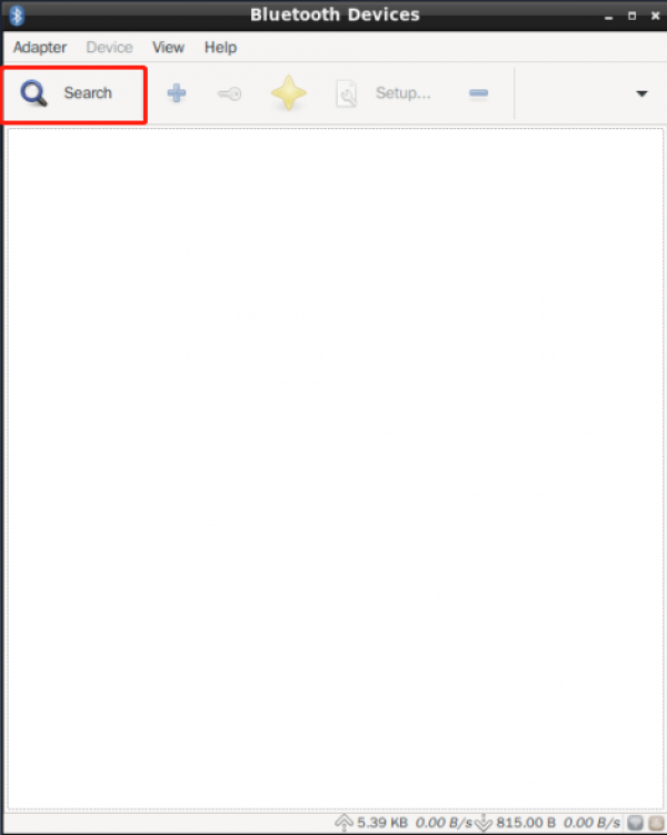
1. Open the Bluetooth manager and search for nearby Bluetooth devices:
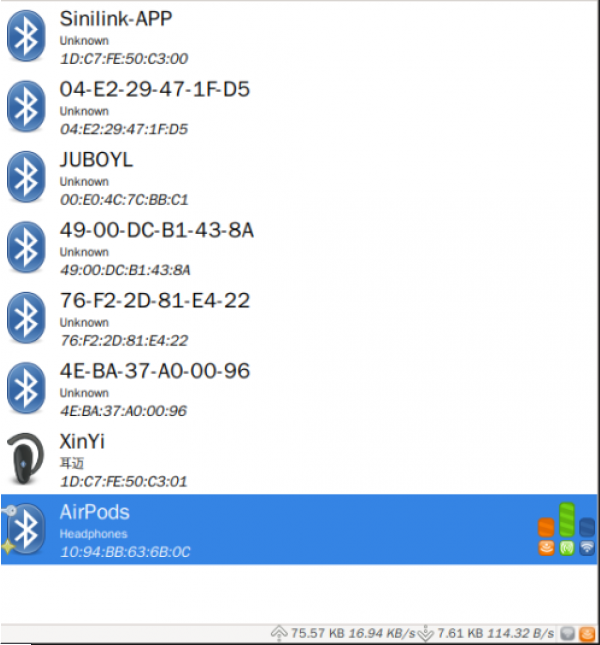
2. Select Bluetooth device, pair and then select Trust:
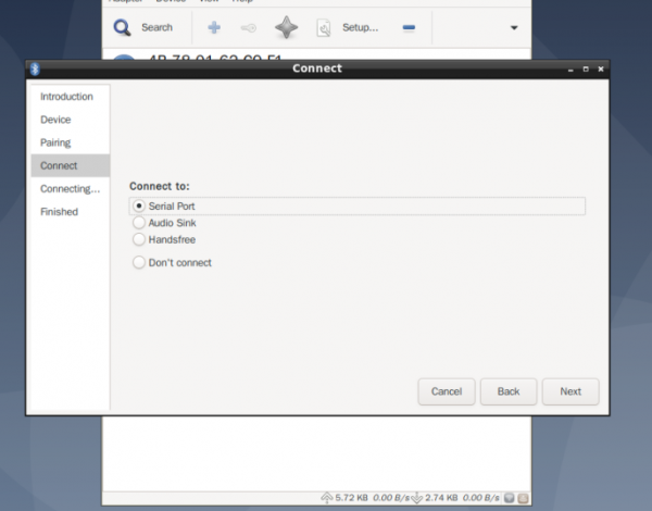
3. To set the Bluetooth connection type:
WatchDog
Key
1. Run the evtest command to view all keys and input devices in the system:
root@rk3399:~# evtest
No device specified, trying to scan all of /dev/input/event*
Available devices:
/dev/input/event0:	ff420030.pwm
/dev/input/event1:	USB Optical Wheel Mouse
/dev/input/event2:	SIGMACH1P USB Keyboard
/dev/input/event3:	rk29-keypad
/dev/input/event4:	SIGMACH1P USB Keyboard
Select the device event number [0-4]:
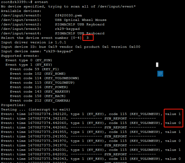
2. Select a test key as prompted. For example, the RK3399 boot key is /dev/input/event3: rk29-keypad
The event number is 3:Pressing the key prints a value of 1,Releasing the key prints a value of 0,As shown below:
3. Customize the key function. The configuration file is
/etc/triggerhappy/triggers.d/example.conf
The key is the reboot function. It is also the default configuration of the system. You can customize the key as required。
KEY_VOLUMEUP 1 reboot
LCD/Backlight
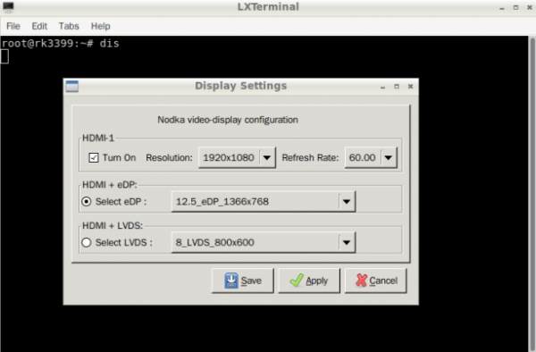
1. The system supports switching between different LCD screens using APP. Run the dis command to open the APP as shown in the following figure:
- Select the corresponding eDP/LVDS screen resolution and click Save. After the system restarts automatically, you can switch to the specified LCD:
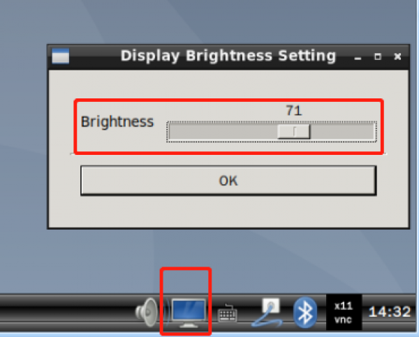
2. Backlight brightness adjustment:
- Method 1: Click the following icon in the system tray at the lower right corner to open the backlight adjustment APP
- Method 2: Control driver application layer interface:
echo 100 > /sys/class/backlight/backlight1/brightness
(Note: The larger the value written, the greater the brightness,max_brightness 为250)
PowerManager
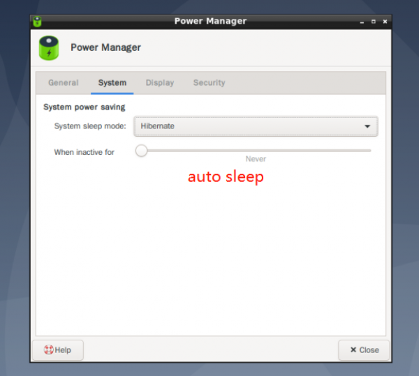
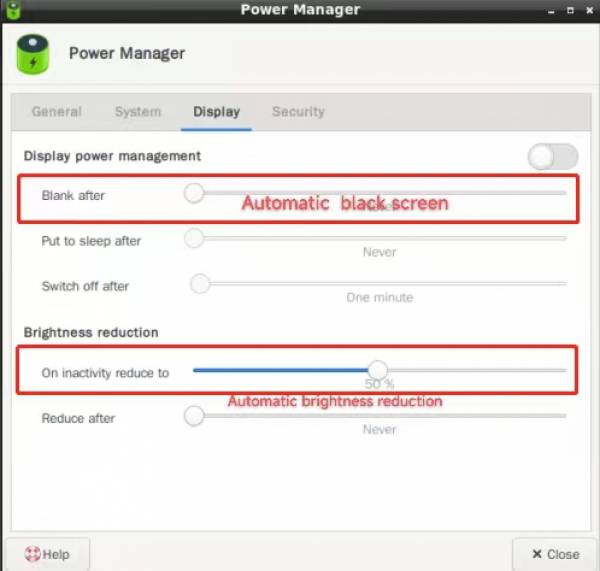
1. Power management Settings:
Press POWER to wake up after sleep 2. The power management function is not supported by all products. To customize the system, contact the service window personnel.
RTC/Timezone
1.View the current system time:
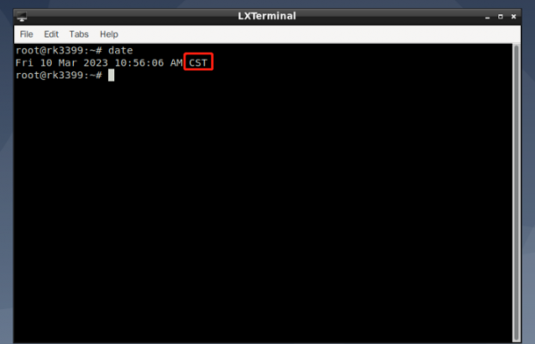
[root@rk3399:~]# date
Wed Jun  8 15:54:09 CST 2022
2. To set the synchronization hardware clock:
[root@rk3399:/]# date -s "2022-06-08 17:01:01"
Wed Jun  8 17:01:01 CST 2022
[root@rk3399:/]# hwclock -w
[root@rk3399:/]# hwclock -r
Wed Jun  8 17:01:09 2022  0.000000 seconds
3. Power off for more than 5 seconds, and then turn it on to check whether the system time is saved:
[root@rk3399:/]# date
 Wed Jun  8 17:02:30 CST 2022
Note: The system uses network time synchronization by default. The above RTC test needs to be conducted when the external network is disconnected. 4. Time zone setting
- Method 1 – Modify the link file, such as China, Shanghai:
ln -sf /usr/share/zoneinfo/Asia/Shanghai /etc/localtime
reboot
To set other time zones, simply change Asia/Shanghai in the preceding command to the corresponding time zone city.
- Method 2 – Open preferences -> in sequence on the graphical interface; Time and date, select the time zone as shown below:
Close the window and run the date command to view the time zone change:
CPU
To view CPU information:
cat /proc/cpuinfo
Memory
Check the memory capacity:
free -h
EMMC
View the available capacity of the EMMC
df -h
Linux Programming guide
GPIO Application programming
C The reference code is as follows:
#include <stdio.h>
#include <stdlib.h>
#include <sys/types.h>
#include <sys/stat.h>
#include <fcntl.h>
#include <unistd.h>
#include <string.h>
static char gpio_path[100];
//Set the GPIO direction and high and low level
static int gpio_config(const char *file, const char *value)
{
	char config_path[100];
	int len;
	int fd;
	sprintf(config_path, "%s/%s", gpio_path, file);
	if (0 > (fd = open(config_path, O_WRONLY)))
	{
		perror("open error");
		return fd;
	}
	len = strlen(value);
	if (len != write(fd, value, len))
	{
		perror("write error");
		close(fd);
		return -1;
	}
	close(fd);
	return 0;
}
//Get the direction and level of GPIO
static int gpio_get(const char *file)
{
	char get_path[100];
	char buf[10]={"\0"};
	int len;
	int fd;
	sprintf(get_path, "%s/%s", gpio_path, file);
	if (0 > (fd = open(get_path, O_RDWR)))
	{
		perror("open error");
		return fd;
	}
	if ( 0 > read(fd,buf,10))
	{
		perror("read error");
		return fd;
	}
	printf("  %s : %s",file,buf);
	close(fd);
	return 0;
}
int main(int argc, char *argv[])
{
	 if (4 != argc)
	{
		if (3 != argc)
		{
			fprintf(stderr, "set gpio out : %s <gpio> <out> <value>\n", argv[0]);
			fprintf(stderr, "set gpio in  : %s <gpio> <in>\n", argv[0]);
			exit(-1);
		}
	}
	sprintf(gpio_path, "/sys/class/gpio/gpio%s", argv[1]);
	if (access(gpio_path, F_OK))
	{
		printf("%s inexistence,export %s... \n",gpio_path,argv[1]);
		int fd;
		int len;
		if (0 > (fd = open("/sys/class/gpio/export", O_WRONLY)))
		{
			perror("open error"); exit(-1);
		}
		len = strlen(argv[1]);
		if (len != write(fd, argv[1], len))
		{
			perror("write error");
			close(fd);
			exit(-1);
		}
		close(fd);
	}
	if (gpio_config("direction", argv[2]))
		exit(-1);
	if ( 0 == strcmp("out",argv[2] ) && argc == 4 )
	{
		if(gpio_config("value", argv[3]))
		exit(-1);
	}
	printf("gpio_op%s:\n",argv[1]);
	if (gpio_get("direction"))
		exit(-1);
	if (gpio_get("value"))
		exit(-1);
	 exit(0);
}
Cross-compiled source code:
aarch64-linux-gnu-gcc -o a.out gpio.c
Copy the compiled gpio program to rk3399 motherboard using scp and perform the test:How to use:
0:./gpio 0 out 0
1:./gpio 0 out 1
UART Application programming
Operating the test serial port of the UART in the system, using the COM2 test as an example:
COM2 The device node is:
/dev/ttyXRUSB1
C Reference UART high and low level input codes are as follows:
#include <sys/types.h>
#include <sys/stat.h>
#include <fcntl.h>
#include <unistd.h>
#include <termios.h>
#include <stdio.h>
#include <string.h>
#include <stdlib.h>

#define UART_DEVICE     "/dev/ttyXRUSB1" //UART Device file name

int main(int argc, char *argv[])
{

    int fd, res;
    struct termios  oldtio, newtio;
    char  ch;
    char buf[256] = {0};

//-----------Open the uart device file------------------
    fd = open(UART_DEVICE, O_RDWR|O_NOCTTY);//No setting O_NONBLOCK。So here read and write are blocking operations
    if (fd < 0) {
        perror(UART_DEVICE);
        exit(1);
    }
    else
    	printf("Open %s successfully\n", UART_DEVICE);

//-----------Set operating parameters-----------------------
    tcgetattr(fd, &oldtio);//Gets the current operation mode parameters
    memset(&newtio, 0, sizeof(newtio));

	//Baud rate =115200 Data bits =8 Enable data receiving
    newtio.c_cflag = B115200|CS8|CLOCAL|CREAD;
    newtio.c_iflag = IGNPAR;

    tcflush(fd, TCIFLUSH);//Clear the input and output buffers
    tcsetattr(fd, TCSANOW, &newtio);//Set a new operation parameter

//------------Send data to urat-------------------
    res=write(fd, "Begin Uart tx", 16);
    while(1) {
    	// Get the data from the console terminal and send it through the uart until it is received! Character
        while((ch=getchar()) != '!') {
            buf[0]=ch;
            res=write(fd, buf, 1);
        }

        buf[0]=ch;
        buf[1]=' ';
        res = write(fd, buf, 2);
        break;
    }
//-------------Receive data from the uart-------------------
    while(1) {
    	res = read(fd, buf, 255);//Here the program will hang until data is received from the uart (blocking operation)
    	if (res == 0)
  			continue;

  		buf[res] = ' ';
  		printf("res = %d, buf = %s\n", res, buf);//Print out the characters received by the uart
  		if (buf[0] == '!')//uart received! Exit the while after the character
  			break;
  	}
//------------Close the uart device file and restore the original parameters--------
    close(fd);
    printf("Close %s\n", UART_DEVICE);
    tcsetattr(fd, TCSANOW, &oldtio); //Restore the original Settings

    return 0;
}

}
Cross-compile source code:
aarch64-linux-gnu-gcc -o uart uart.c
Copy the compiled program to 3399 motherboard using scp, and perform the test:
KEY application programming
For details, see the method of operating a key in the system
/dev/input/event2
C The reference code is as follows:
#include <unistd.h>
#include <fcntl.h>
#include <stdio.h>
#include <stdlib.h>
#include <linux/input.h>
#include <sys/select.h>
#define INPUT_DEVICE "/dev/input/event2"
int main(int argc, char **argv){
	int fd;
	struct input_event event;
	ssize_t bytesRead;
	int ret;
	fd_set readfds;
	if ( 0 > (fd = open(INPUT_DEVICE,O_RDONLY)))
	{
		perror("open error");
		return fd;
	}
	while(1){
		FD_ZERO(&readfds);
		FD_SET(fd,&readfds);
		ret = select(fd + 1, &readfds, NULL, NULL, NULL);
		if (ret == -1){
			fprintf(stderr,"select call on%s : an error ocurred",argv[1]);
		break;
		}
		if(FD_ISSET(fd,&readfds)){
			bytesRead = read(fd, &event,sizeof(struct input_event));
			if(bytesRead == -1 )
				fprintf(stderr,"bytesRead :%ld : an error ocurred",bytesRead);
			}
		if(event.type == EV_KEY && (event.value == 0 || event.value == 1))
		{
			printf("key %s\n",(event.value) ? "pressed" : "released");
		}
	}
	close(fd);
	return EXIT_SUCCESS;
}
Cross-compile source code:
aarch64-linux-gnu-gcc -o key key.c
Copy the compiled program to the r39s2 motherboard using scp, perform the test, press the key to print as follows:
- Display when the key is pressed:key pressed
- Display when the key is released:key released
Linux Application support
QT Cross-compilation environment
* Host environment recommendation:Debian 10 x64 bit,
 The company has configured the QT compilation environment- Docker image:[[ftp://drv.nodka.com/arm_download/nodka_docker_qt_build_20230223.tar |  QT编译环境Docker]]
 ### load docker image
 sudo docker load <nodka_docker_qt_build_20230223.tar

 ### Run the docker image,notice : /home/APP_PATH为QT-Directory where the application program resides
 sudo docker run --rm --mount type=bind,source=/home/APP_PATH,target=/mnt/ -i -t 09a37c1b2fc3 /bin/bash

 ###  Compile the QT application
 cd  /mnt
 qmake
 make
* Refer to the steps for configuring the host cross-compilation environment:
1. Install the cross-compile toolchain:
apt install -y crossbuild-essential-arm64
2. Copy /usr/lib/lib from the tablet system to the host /home/nodk/qt5/qt_sysroot directory
3. Configure the following environment variables
QTSYSROOT="/home/nodka/qt5/qt_sysroot"
QTPATH=$QTSYSROOT/usr/local/qt5.12-arm

LD_LIBRARY_PATH=$QTPATH/lib:$LIBRARY_PATH
LIBRARY_PATH=$QTPATH/lib:$LIBRARY_PATH
C_INCLUDE_PATH=$QTPATH/include:$C_INCLUDE_PATH
PATH=$QTPATH/bin:$PATH

PKG_CONFIG_PATH=$QTPATH/lib/pkgconfig:$PKG_CONFIG_PATH

export LD_LIBRARY_PATH
export LIBRARY_PATH
export C_INCLUDE_PATH
export CPLUS_INCLUDE_PATH

export PKG_CONFIG_PATH
export PATH
4. Compile APP
qmake
make
QT Creator
1. install
Go to the Qt official download page and select a version to download qt- creator-opensource-linux-x86_64-x.x.x.un. After the download is complete, run./xxxx.run on the terminal to run the installation.
2.configuration
After the installation is complete, start Qt Creator and open the menu Tools-> Option, find the Kits.
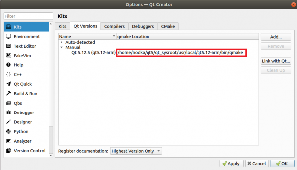
- configuration Qt Versions
Click the add button on the right and select qmake in the installation location of the Qt environment
qmake:
/usr/local/qt5.12-arm/bin/qmake
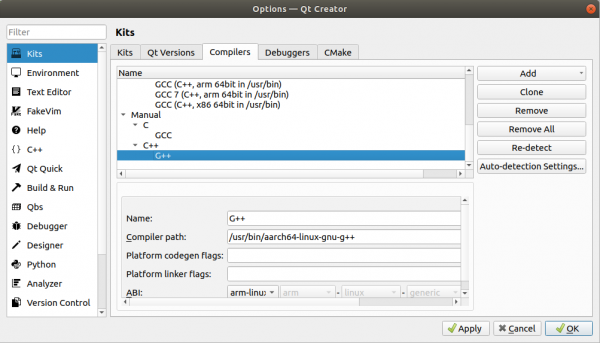
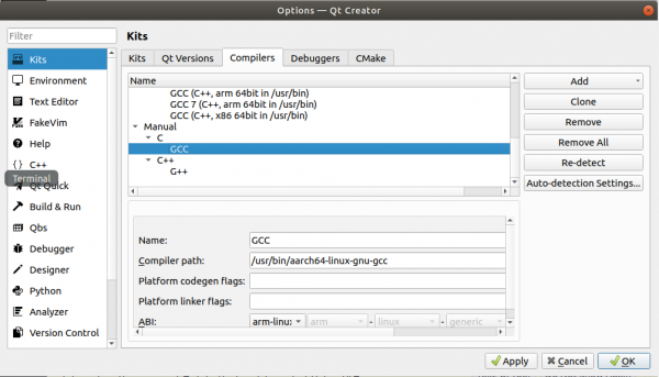
- configuration Compilers
Click the add button on the right to add the location of the gcc and g++ cross compiler
If crossbuild-essential arm64 is installed on the host, the compiler is under /usr/bin/
If you use a third-party cross-compiler, find the installation location and add it
If the target platform is Buildroot, you will need to use the compiler in the Buildroot Qt environment package
g++:/usr/bin/aarch64-linux-gnu-g++
gcc:/usr/bin/aarch64-linux-gnu-gcc
To facilitate debugging, configure Debeggers and Devices for online debugging:
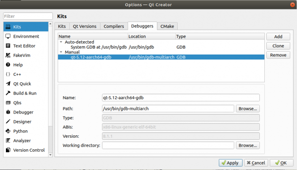
- configuration Debuggers
Click the add button on the right to add gbd-multiarch: apt install -y gdb-multiarch
Check whether /usr/bin/gdbserver exists on the target. If not, install: apt install -y gdbserver. If not, install: apt install -y gdbserver (Buildroot comes with Buildroot)
Go back to Qt Creator on the host and click the add button on the right to add gdb
Select gdb-multiarch: /usr/bin/gdb-multierch on the host
- configuration Devices
Set the IP address and user name of the device (root). To facilitate debugging, set a static IP address on the device.
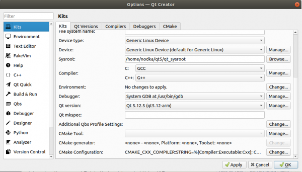
- configuration Kits
Add the configuration item set earlier to Kits.
If the target platform is an Ubuntu system, this step also requires adding the sysroot path
HD hard decoding
Docker
Docker English-Community supports the following versions of Ubuntu:
- Xenial 16.04(LTS)
- Bionic 18.04(LTS)
- Cosmic 18.04
- Disco 19.04
- Other newer versions…
The installation command is as follows:
curl -fsSL https://get.docker.com | bash -s docker --miror Aliyun
You can also use the domestic daocloud one-click install command:
curl -sSL https://get.daocloud.io/docker | sh
To test whether Docker is successfully installed, enter the following command and print the following information:
sudo docker run hello-world

Unable to find image 'hello-world:latest' locally
latest: Pulling from library/hello-world
1b930d010525: Pull complete
Digest: sha256:c3b4ada4687bbaa170745b3e4dd8ac3f194ca95b2d0518b417fb47e5879d9b5f
Status: Downloaded newer image for hello-world:latest


Hello from Docker!
This message shows that your installation appears to be working correctly.


To generate this message, Docker took the following steps:
 1. The Docker client contacted the Docker daemon.
 2. The Docker daemon pulled the "hello-world" image from the Docker Hub.
    (amd64)
 3. The Docker daemon created a new container from that image which runs the
    executable that produces the output you are currently reading.
 4. The Docker daemon streamed that output to the Docker client, which sent it
    to your terminal.


To try something more ambitious, you can run an Ubuntu container with:
 $ docker run -it ubuntu bash


Share images, automate workflows, and more with a free Docker ID:
 https://hub.docker.com/


For more examples and ideas, visit:
 https://docs.docker.com/get-started/
