目录
Linux Usage guide
Interface function test
GPIO
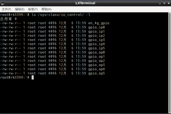
1.IO The control nodes are all present:/sys/class/io_control
2.IO corresponds to the following table:
| function | Screen printing of motherboard | Node name |
|---|---|---|
| input | IO1 | gpio_ip0 |
| IO2 | gpio_ip1 | |
| IO3 | gpio_ip2 | |
| IO4 | gpio_ip3 | |
| IO5 | gpio_ip4 | |
| IO6 | gpio_ip5 | |
| output | IO7 | gpio_op0 |
| IO8 | gpio_op1 | |
| IO9 | gpio_op2 | |
| IO10 | gpio_op3 | |
| IO11 | gpio_op4 | |
| IO12 | gpio_op5 |
3.IO control method:
- Output low level:
echo 0 >/sys/class/io_control/gpio_op0
*Output high level:
echo 1 >/sys/class/io_control/gpio_op0
*View input level:
cat /sys/class/io_control/gpio_ip0
UART
1. Serial port definition reference:
2. Serial port device node system mapping table:
| Screen printing of motherboard | Device node |
|---|---|
| COM1 | /dev/ttyXRUSB0 |
| COM2 | /dev/ttyXRUSB1 |
| COM3 | /dev/ttyXRUSB2 |
| COM4 | /dev/ttyXRUSB3 |
3. CuTecom tests the serial port, The COM2 loopback test is used as an example
- Refer to Steps 1 to 2 to short the TX & RX (2 to 3 pin) of COM2.
- Double-click the CuteCom icon on the desktop, open APP, Device select the device node corresponding to the test port (see Step 2).
- Click Settings to set the serial port parameters, as shown in the picture below:
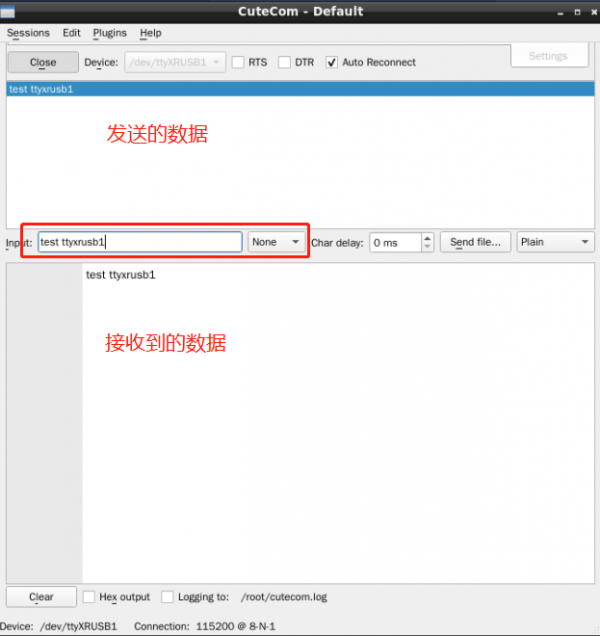
- Click Open to open the serial port, input characters in the input text box, and press Enter to send data:
4. Test the serial port on the CLI, The COM2 loopback test is used as an example
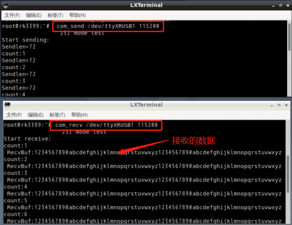
Open the terminal and enter the following command to receive data:
com_recv /dev/ttyXRUSB1 115200
Open another terminal to send data:
com_send /dev/ttyXRUSB1 115200
The test results are as follows:
LAN
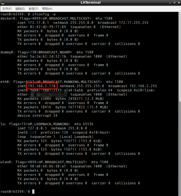
1. Check the IP address of the network adapter, The system dynamically obtains an IP address by default
#ifconfig -a
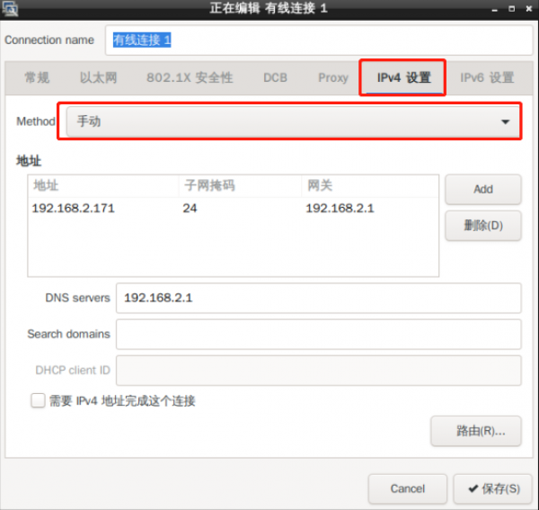
2. Set a static IP address for a network adapter
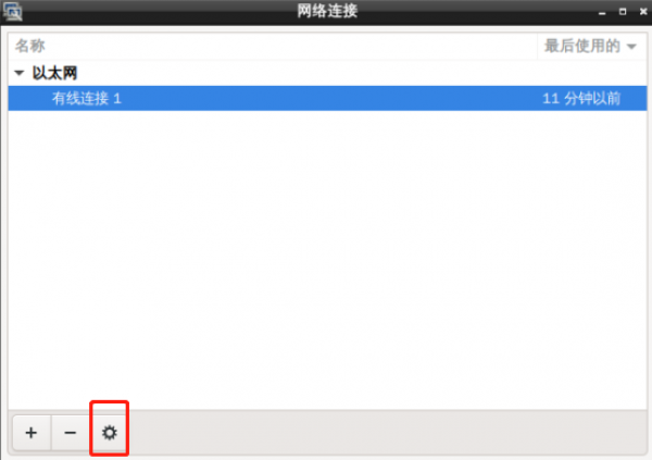
- Method 1 – Use graphical tool Settings
Double-click the desktop icon:Advanced Network Configuration
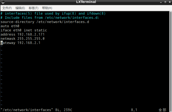
- Method 2 – How to modify the configuration file:
vim /etc/network/interfaces
- After the modification is complete, enter restart to take effect.
WIFI
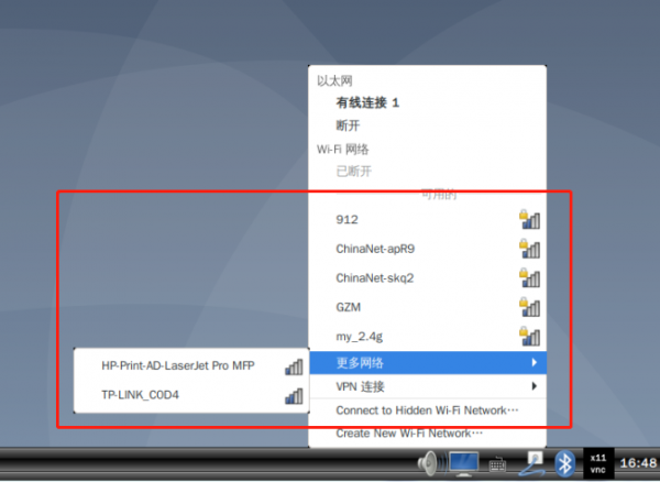
1. Click the network icon in the lower right corner to browse the available WIFI routes:
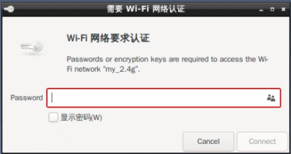
- Enter your WIFI password and tap connect
2. Method 2 – Connect to wifi from the command line
nmcli d wifi connect "SSID" password "PASSWROD"
4G/5G
1. The system has automatic dialing, Open the terminal and enter the command 4g to dial automatically:
root@rk3399:~# 4g
2. After the dial-up is complete, view the IP address:
3.Open a browser and browse any website.
4. The test method of 5G is similar to that of 4G, Input the command 5g to dial automatically:
root@rk3399:~# 5g
Can
GPIO/DIO
1.IO - The control nodes are all present:/sys/class/io_control
2.IO - corresponds to the following table:
| function | Screen printing of motherboard | Node name |
|---|---|---|
| input | IO1 | gpio_ip0 |
| IO2 | gpio_ip1 | |
| IO3 | gpio_ip2 | |
| IO4 | gpio_ip3 | |
| IO5 | gpio_ip4 | |
| IO6 | gpio_ip5 | |
| output | IO7 | gpio_op0 |
| IO8 | gpio_op1 | |
| IO9 | gpio_op2 | |
| IO10 | gpio_op3 | |
| IO11 | gpio_op4 | |
| IO12 | gpio_op5 |
3.IO control method:
- Output low level:
echo 0 >/sys/class/io_control/gpio_op0
*Output high level:
echo 1 >/sys/class/io_control/gpio_op0
*View input level:
cat /sys/class/io_control/gpio_ip0
Audio
- Connect the horn to the SPK port on the board
1. Method ① – Use the SMPayer player delivered with the system and the audio test file to test the audio function
2. Method 2 – Using commands to play:
aplay /nodka_test/LR_audio.wav -D hw:0,0
Mic
- Recording test
arecord -d 5 -f cd -r 44100 -c 2 -t wav test.wav
aplay test.wav
USB
1. The USB flash drive is automatically mounted to /media/disk
root@rk3399:~# df -h
File system        capacity  used  available used% Mount point
/dev/root        15G  3.6G   10G   27% /
devtmpfs        980M     0  980M    0% /dev
tmpfs           981M     0  981M    0% /dev/shm
tmpfs           981M  8.8M  972M    1% /run
tmpfs           5.0M  4.0K  5.0M    1% /run/lock
tmpfs           981M     0  981M    0% /sys/fs/cgroup
tmpfs           197M   16K  197M    1% /run/user/0
/dev/sda1        57G  2.7G   54G    5% /media/disk
SDCARD
* SDcard Automatic mounting:
root@rk3399:~# df -h
File system        capacity  used  available used% Mount point
/dev/root        15G  3.6G   10G   27% /
devtmpfs        980M     0  980M    0% /dev
tmpfs           981M     0  981M    0% /dev/shm
tmpfs           981M  8.8M  972M    1% /run
tmpfs           5.0M  4.0K  5.0M    1% /run/lock
tmpfs           981M     0  981M    0% /sys/fs/cgroup
tmpfs           197M   16K  197M    1% /run/user/0
/dev/mmcblk0p8   30G  3.8G   25G   14% /media/3699f79c-f05d-4948-89c9-04dc4b132a1f
umount:
umount /dev/mmcblk0p8
mount:
mount /dev/mmcblk0p8 /sdcard
Bluetooth
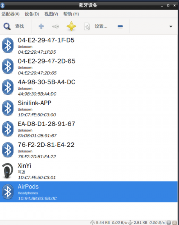
1. Open the Bluetooth manager and search for nearby Bluetooth devices:
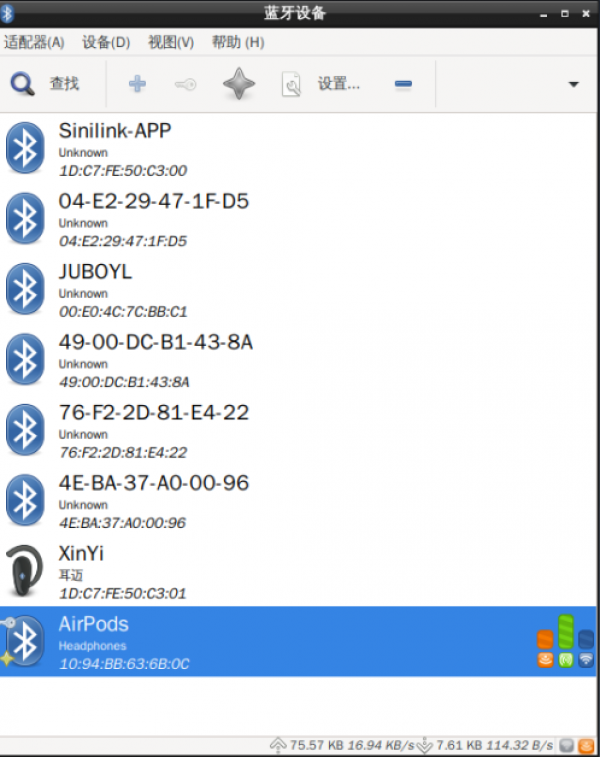
2. Select Bluetooth device, pair and then select Trust:
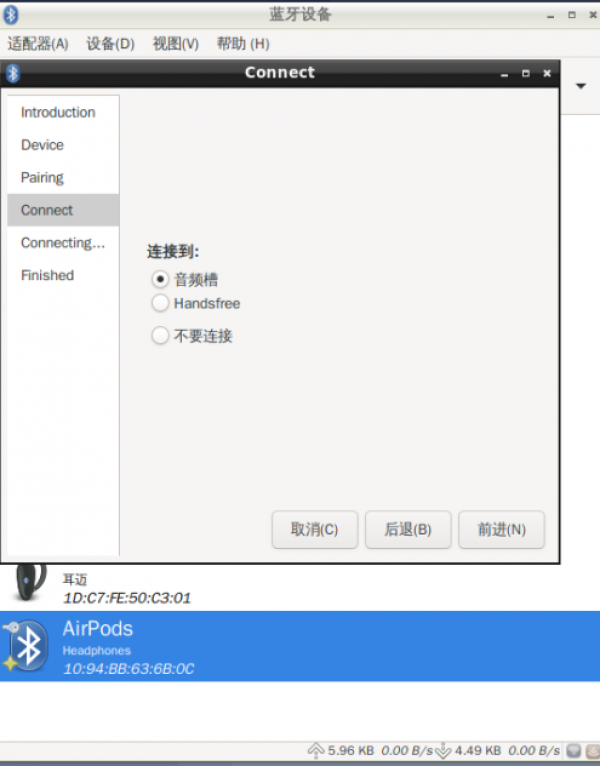
3. To set the Bluetooth connection type:
WatchDog
Key
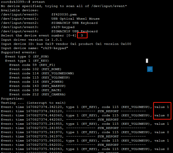
1. Run the evtest command to view all keys and input devices in the system:
root@rk3399:~# evtest
No device specified, trying to scan all of /dev/input/event*
Available devices:
/dev/input/event0:	ff420030.pwm
/dev/input/event1:	USB Optical Wheel Mouse
/dev/input/event2:	SIGMACH1P USB Keyboard
/dev/input/event3:	rk29-keypad
/dev/input/event4:	SIGMACH1P USB Keyboard
Select the device event number [0-4]:
2. Select a test key as prompted. For example, the RK3399 boot key is /dev/input/event3: rk29-keypad
The event number is 3:Pressing the key prints a value of 1,Releasing the key prints a value of 0,As shown below:
3. Customize the key function. The configuration file is
/etc/triggerhappy/triggers.d/example.conf
The key is the reboot function. It is also the default configuration of the system. You can customize the key as required。
KEY_VOLUMEUP 1 reboot
LCD/Backlight
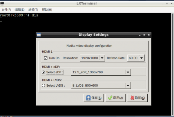
1. The system supports switching between different LCD screens using APP. Run the dis command to open the APP as shown in the following figure:
- Select the corresponding eDP/LVDS screen resolution and click Save. After the system restarts automatically, you can switch to the specified LCD:
2. Backlight brightness adjustment:
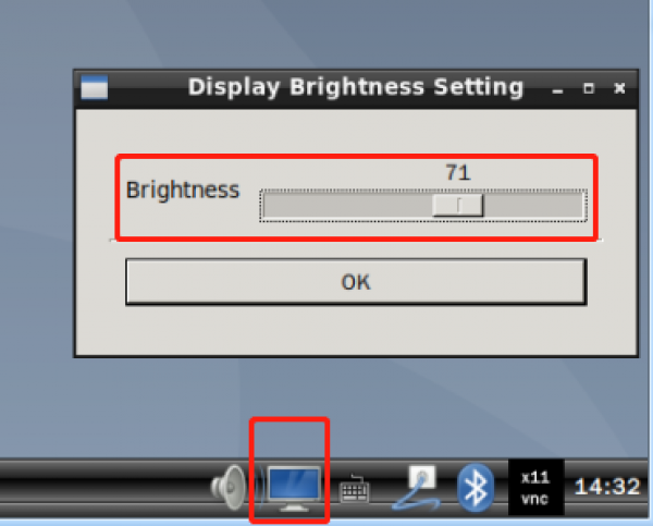
- Method 1: Click the following icon in the system tray at the lower right corner to open the backlight adjustment APP
- Method 2: Control driver application layer interface:
echo 100 > /sys/class/backlight/backlight1/brightness
(Note: The larger the value written, the greater the brightness,max_brightness 为250)
PowerManager
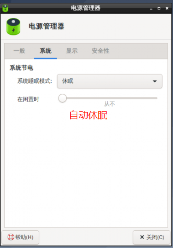
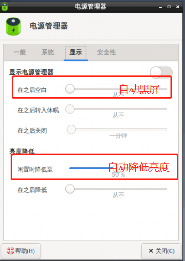
1. Power management Settings:
Press POWER to wake up after sleep 2. The power management function is not supported by all products. To customize the system, contact the service window personnel.
RTC/Timezone
1.View the current system time:
[root@rk3399:~]# date
Wed Jun  8 15:54:09 CST 2022
2. To set the synchronization hardware clock:
[root@rk3399:/]# date -s "2022-06-08 17:01:01"
Wed Jun  8 17:01:01 CST 2022
[root@rk3399:/]# hwclock -w
[root@rk3399:/]# hwclock -r
Wed Jun  8 17:01:09 2022  0.000000 seconds
3. Power off for more than 5 seconds, and then turn it on to check whether the system time is saved:
[root@rk3399:/]# date
 Wed Jun  8 17:02:30 CST 2022
Note: The system uses network time synchronization by default. The above RTC test needs to be conducted when the external network is disconnected. 4. Time zone setting
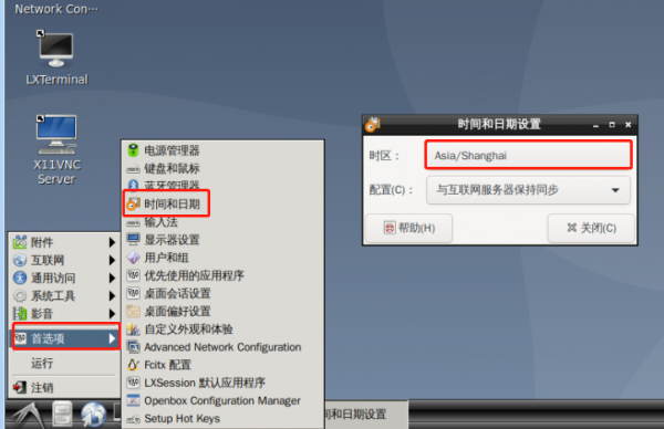
- Method 1 – Modify the link file, such as China, Shanghai:
ln -sf /usr/share/zoneinfo/Asia/Shanghai /etc/localtime
reboot
To set other time zones, simply change Asia/Shanghai in the preceding command to the corresponding time zone city.
- Method 2 – Open preferences -> in sequence on the graphical interface; Time and date, select the time zone as shown below:
Close the window and run the date command to view the time zone change:
CPU
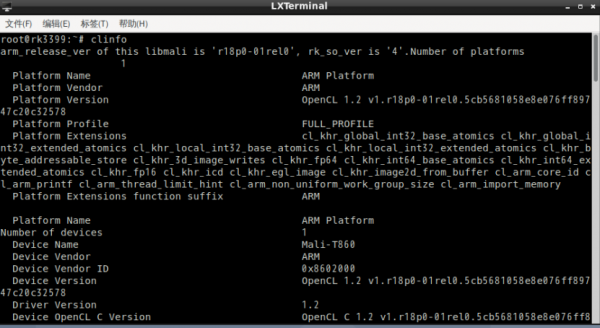
To view CPU information:
cat /proc/cpuinfo
Memory
Check the memory capacity:
free -h
EMMC
View the available capacity of the EMMC
df -h
Linux Programming guide
GPIO Application programming
C The reference code is as follows:
#include <stdio.h>
#include <stdlib.h>
#include <sys/types.h>
#include <sys/stat.h>
#include <fcntl.h>
#include <unistd.h>
#include <string.h>
static char gpio_path[100];
//Set the GPIO direction and high and low level
static int gpio_config(const char *file, const char *value)
{
	char config_path[100];
	int len;
	int fd;
	sprintf(config_path, "%s/%s", gpio_path, file);
	if (0 > (fd = open(config_path, O_WRONLY)))
	{
		perror("open error");
		return fd;
	}
	len = strlen(value);
	if (len != write(fd, value, len))
	{
		perror("write error");
		close(fd);
		return -1;
	}
	close(fd);
	return 0;
}
//Get the direction and level of GPIO
static int gpio_get(const char *file)
{
	char get_path[100];
	char buf[10]={"\0"};
	int len;
	int fd;
	sprintf(get_path, "%s/%s", gpio_path, file);
	if (0 > (fd = open(get_path, O_RDWR)))
	{
		perror("open error");
		return fd;
	}
	if ( 0 > read(fd,buf,10))
	{
		perror("read error");
		return fd;
	}
	printf("  %s : %s",file,buf);
	close(fd);
	return 0;
}
int main(int argc, char *argv[])
{
	 if (4 != argc)
	{
		if (3 != argc)
		{
			fprintf(stderr, "set gpio out : %s <gpio> <out> <value>\n", argv[0]);
			fprintf(stderr, "set gpio in  : %s <gpio> <in>\n", argv[0]);
			exit(-1);
		}
	}
	sprintf(gpio_path, "/sys/class/gpio/gpio%s", argv[1]);
	if (access(gpio_path, F_OK))
	{
		printf("%s inexistence,export %s... \n",gpio_path,argv[1]);
		int fd;
		int len;
		if (0 > (fd = open("/sys/class/gpio/export", O_WRONLY)))
		{
			perror("open error"); exit(-1);
		}
		len = strlen(argv[1]);
		if (len != write(fd, argv[1], len))
		{
			perror("write error");
			close(fd);
			exit(-1);
		}
		close(fd);
	}
	if (gpio_config("direction", argv[2]))
		exit(-1);
	if ( 0 == strcmp("out",argv[2] ) && argc == 4 )
	{
		if(gpio_config("value", argv[3]))
		exit(-1);
	}
	printf("gpio_op%s:\n",argv[1]);
	if (gpio_get("direction"))
		exit(-1);
	if (gpio_get("value"))
		exit(-1);
	 exit(0);
}
Cross-compiled source code:
aarch64-linux-gnu-gcc -o a.out gpio.c
Copy the compiled gpio program to rk3399 motherboard using scp and perform the test:How to use:
0:./gpio 0 out 0
1:./gpio 0 out 1
UART Application programming
Operating the test serial port of the UART in the system, using the COM2 test as an example:
COM2 The device node is:
/dev/ttyXRUSB1
C Reference UART high and low level input codes are as follows:
#include <sys/types.h>
#include <sys/stat.h>
#include <fcntl.h>
#include <unistd.h>
#include <termios.h>
#include <stdio.h>
#include <string.h>
#include <stdlib.h>

#define UART_DEVICE     "/dev/ttyXRUSB1" //UART Device file name

int main(int argc, char *argv[])
{

    int fd, res;
    struct termios  oldtio, newtio;
    char  ch;
    char buf[256] = {0};

//-----------Open the uart device file------------------
    fd = open(UART_DEVICE, O_RDWR|O_NOCTTY);//No setting O_NONBLOCK。So here read and write are blocking operations
    if (fd < 0) {
        perror(UART_DEVICE);
        exit(1);
    }
    else
    	printf("Open %s successfully\n", UART_DEVICE);

//-----------Set operating parameters-----------------------
    tcgetattr(fd, &oldtio);//Gets the current operation mode parameters
    memset(&newtio, 0, sizeof(newtio));

	//Baud rate =115200 Data bits =8 Enable data receiving
    newtio.c_cflag = B115200|CS8|CLOCAL|CREAD;
    newtio.c_iflag = IGNPAR;

    tcflush(fd, TCIFLUSH);//Clear the input and output buffers
    tcsetattr(fd, TCSANOW, &newtio);//Set a new operation parameter

//------------Send data to urat-------------------
    res=write(fd, "Begin Uart tx", 16);
    while(1) {
    	// Get the data from the console terminal and send it through the uart until it is received! Character
        while((ch=getchar()) != '!') {
            buf[0]=ch;
            res=write(fd, buf, 1);
        }

        buf[0]=ch;
        buf[1]=' ';
        res = write(fd, buf, 2);
        break;
    }
//-------------Receive data from the uart-------------------
    while(1) {
    	res = read(fd, buf, 255);//Here the program will hang until data is received from the uart (blocking operation)
    	if (res == 0)
  			continue;

  		buf[res] = ' ';
  		printf("res = %d, buf = %s\n", res, buf);//Print out the characters received by the uart
  		if (buf[0] == '!')//uart received! Exit the while after the character
  			break;
  	}
//------------Close the uart device file and restore the original parameters--------
    close(fd);
    printf("Close %s\n", UART_DEVICE);
    tcsetattr(fd, TCSANOW, &oldtio); //Restore the original Settings

    return 0;
}

}
Cross-compile source code:
aarch64-linux-gnu-gcc -o uart uart.c
Copy the compiled program to 3399 motherboard using scp, and perform the test:
KEY application programming
For details, see the method of operating a key in the system
/dev/input/event2
C The reference code is as follows:
#include <unistd.h>
#include <fcntl.h>
#include <stdio.h>
#include <stdlib.h>
#include <linux/input.h>
#include <sys/select.h>
#define INPUT_DEVICE "/dev/input/event2"
int main(int argc, char **argv){
	int fd;
	struct input_event event;
	ssize_t bytesRead;
	int ret;
	fd_set readfds;
	if ( 0 > (fd = open(INPUT_DEVICE,O_RDONLY)))
	{
		perror("open error");
		return fd;
	}
	while(1){
		FD_ZERO(&readfds);
		FD_SET(fd,&readfds);
		ret = select(fd + 1, &readfds, NULL, NULL, NULL);
		if (ret == -1){
			fprintf(stderr,"select call on%s : an error ocurred",argv[1]);
		break;
		}
		if(FD_ISSET(fd,&readfds)){
			bytesRead = read(fd, &event,sizeof(struct input_event));
			if(bytesRead == -1 )
				fprintf(stderr,"bytesRead :%ld : an error ocurred",bytesRead);
			}
		if(event.type == EV_KEY && (event.value == 0 || event.value == 1))
		{
			printf("key %s\n",(event.value) ? "pressed" : "released");
		}
	}
	close(fd);
	return EXIT_SUCCESS;
}
Cross-compile source code:
aarch64-linux-gnu-gcc -o key key.c
Copy the compiled program to the r39s2 motherboard using scp, perform the test, press the key to print as follows:
- Display when the key is pressed:key pressed
- Display when the key is released:key released
